This article demonstrates a modification of the Arduino SwitecX25 driver library to use a AX1201728SG quad driver chip (equivalent to the X12.017 or VID6606). This chip offers some significant advantages over driving the motor directly:
- it uses microstepping to provide smoother positioning - 12 steps per degree rather than 3.
- it requires only two GPIO pins per motor (plus one global reset pin)
- it protects the microprocessor from the inductive effects of the motor coils
- it places lower current requirements on the microprocessor
In the past I’ve been unable to find a low-volume supplier for the X12.017 Quad Driver Chip, or any of the functionally identical chips from other manufacturers. These are the ones I know about:
- The VID VID6606 Quad Driver (datasheet)
- The NOST Microelectronics BY8920 Quad Driver (datasheet, in Chinese)
- The AX1201728SG (by EmMicroe maybe?)
Recently both the AX1201728SG and VID6606 have become readily available in small quantities.
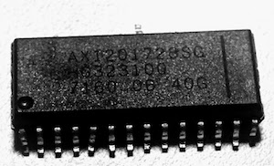
The AX1201728SG
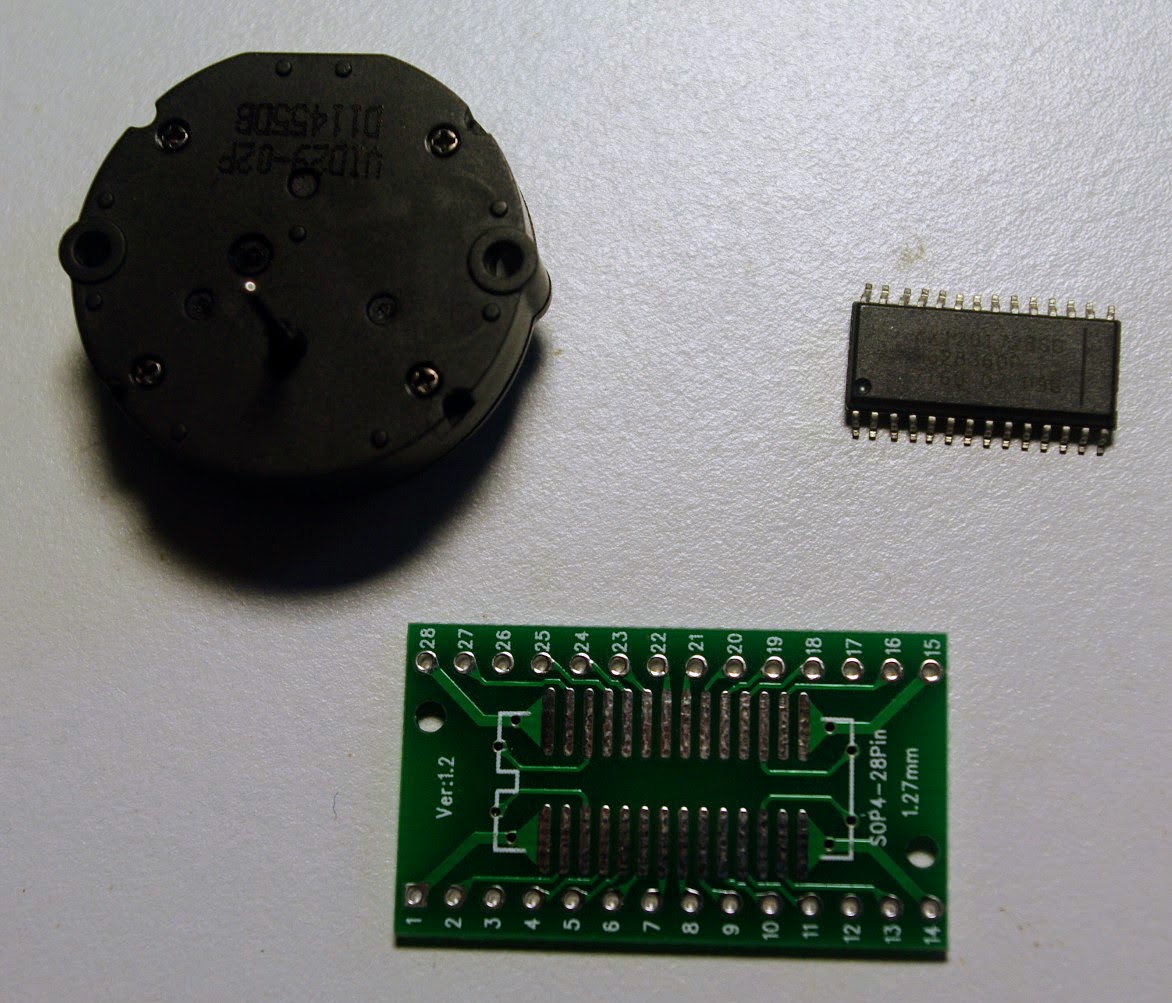
The AX1201728SG is available in single quantities from ebay for a few dollars apiece. The one complication is that they are SOP28 surface mount packages, which are a little harder to prototype with than DIP packages. I bought some drivers, and some SOP28 to DIP28 adaptors so I could mount the drivers on a breadboard for testing.
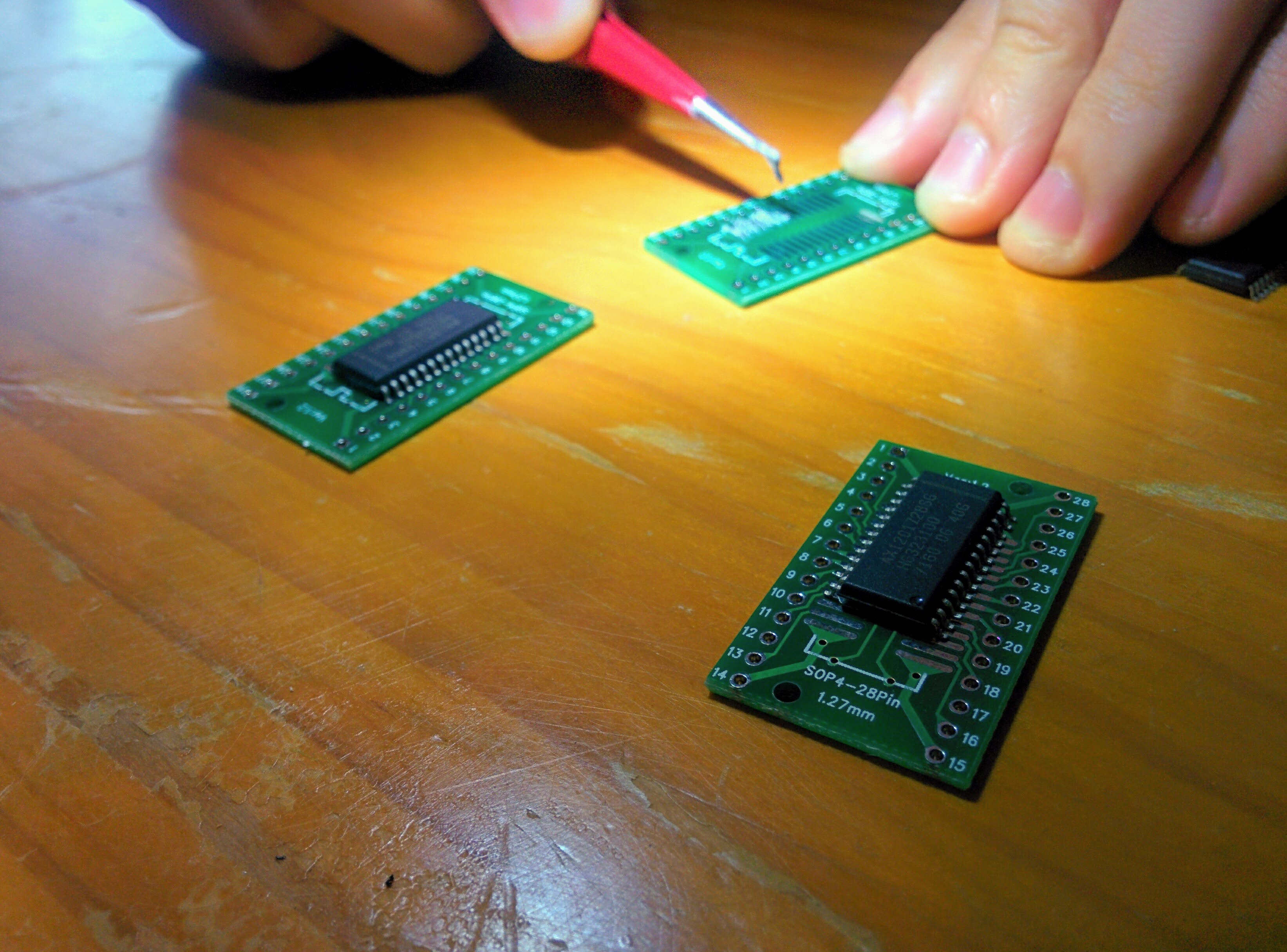
Mounting
I haven’t worked with SMD chips before, so I had a friend help me mount them. We used tweezers to apply the paste, and a regular household oven for reflowing. Very basic, but it worked fine.

Wiring It Up
Initially I’m testing with a single motor on output A. The wiring is as follows:
- VSS (chip pin 12) to GND
- VDD (chip pins 1 and 15) to 5V
- RESET (chip pin 26) to Arduino pin 10
- CW/CCW A (chip pin 27) to Arduino pin 9
- f(scx) A (chip pin 28) to Arduino pin 8
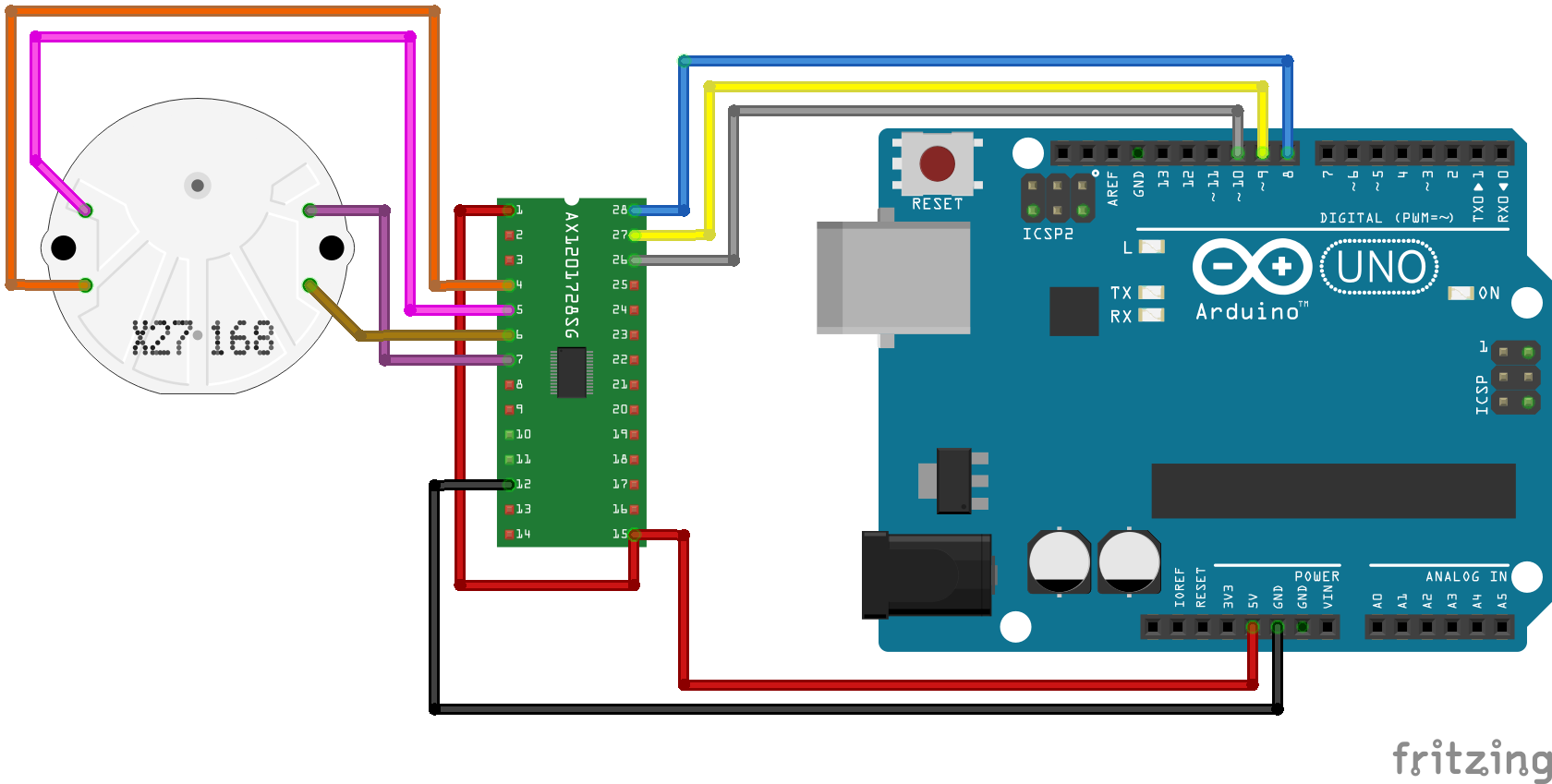
 The motor connections are:
- OUT1A (chip pin 7) to Motor pin 1
- OUT2A (chip pin 6) to Motor pin 2
- OUT3A (chip pin 4) to Motor pin 3
- OUT4A (chip pin 5) to Motor pin 4
Software
I started with a basic hello-world program to run the motor forward and backwards so I could work out any setup issues before switching to the more complicated driver software.
/*
  X12.017 Quad Driver Test
  Drive the motor forward and backwards through 270 degrees
  at constant speed.
 */

const int LED = 13;
const int DIR_A = 9; // pin for CW/CCW
const int STEP_A = 8; // pin for f(scx)
const int RESET = 10; // pin for RESET
const int DELAY = 250; // μs between steps
const int ANGLE = 270; // of 315 available
const int RANGE = ANGLE * 3 * 4;
int steps = 0;
bool forward = true;

// pull RESET low to reset, high for normal operation.

void setup() {
  pinMode(DIR_A, OUTPUT);
  pinMode(STEP_A, OUTPUT);
  pinMode(LED, OUTPUT);
  pinMode(RESET, OUTPUT);

  digitalWrite(RESET, LOW);
  digitalWrite(LED, HIGH);
  digitalWrite(STEP_A, LOW);
  digitalWrite(DIR_A, HIGH);
  delay(1);  // keep reset low min 1ms
  digitalWrite(RESET, HIGH);
}

// The motor steps on rising edge of STEP
// The step line must be held low for at least 450ns
// which is so fast we probably don't need a delay,
// put in a short delay for good measure.

void loop() {
  digitalWrite(STEP_A, LOW);
  delayMicroseconds(1);  // not required

  steps++;
  if (steps > RANGE) {
    forward = !forward;
    steps = 0;
    digitalWrite(DIR_A, forward ? LOW : HIGH);
    digitalWrite(LED, forward ? HIGH : LOW);
  }

  digitalWrite(STEP_A, HIGH);
  delayMicroseconds(DELAY);
}
This worked, mostly. If I leave the motor running for a while I notice that the needle position drifts, which indicates either missed steps, or a counting problem. Increasing the inter-step delay from 250ms to 500ms resolved that problem, so most likely I’m exceeding the (low) torque limit during the turnaround. I’m not worried about that - once I port the SwitecX25 library I can find a safe set of acceleration parameters to keep it from dropping steps.
Adapting the SwitecX25 Library
The SwitecX25 library provides an acceleration/deceleration model,
and some higher-level control abstractions. Importantly, it is asynchronous.
The caller sets a desired step position and then calls the update() method
as frequently as possible and the library manages the scheduling of the steps.
One concern I have about supporting the quad driver is the being able to service the pin transitions quickly enough. When driving the motor directly we need to update 4 outputs once per step. With the quad driver we need to pulse the f(scx) line low then high once per micro-step, which equates to 8 transitions per full step. It may turn out to be difficult hit all of the timing deadlines to drive 4 motors at full speed simultaneously.
My first cut at this is to create an entirely new class SwitecX12 which duplicates the key timing code from SwitecX25, with new output logic and an adjusted acceleration curve.
The code below zeroes the needle, moves the needle to the centre of the sweep, then cycles between ¼ range and ¾ range.
#include <SwitecX12.h>

const int STEPS = 315 * 12;
const int A_STEP = 8;
const int A_DIR = 9;
const int RESET = 10;

SwitecX12 motor1(STEPS, A_STEP, A_DIR);


void setup() {
  digitalWrite(RESET, HIGH);
  Serial.begin(9600);
  motor1.zero();
  motor1.setPosition(STEPS/2);
}

void loop() {
  static bool forward = true;
  static int position1 = STEPS * 3/4;
  static int position2 = STEPS * 1/4;
  if (motor1.stopped) {
    motor1.setPosition(forward ? position1 : position2);
    forward = !forward;
  }
  motor1.update();
}
Conclusion
The AX1201728SG looks very promising. It’s a bit of a nuisance to deal with surface mount devices if you aren’t set up for it, but not insurmountable.
The microstepping is really smooth. Below is a video showing how smooth. I used a very exaggerated acceleration table to keep the needle in the slow range for longer.