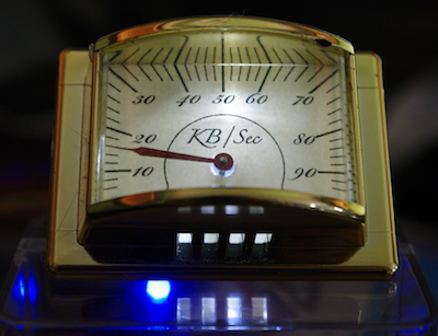
I’ve been intending to try driving Switec X25.168 motors using the MCP23008 I²C I/O port expander chip from an Arduino, but it occurs to me that it might be more interesting to try this on a Rasberry Pi. If it works, it will demonstrate a simple and very inexpensive method for driving analog gauges from the Raspberry Pi without the need for high-current drivers.
The MCP23008 provides 8 I/O lines controlled via an I²C interface.
The datasheet is available here
.
The pins are rated to source and sink 20mA each. That’s around half what an Arduino offers, but
should be (just) enough to drive our little Switec steppers.
These chips are available from Adafruit,
along with the doubly awesome 16-port MCP23017.
Since this is my first Raspberry Pi project, I’ll include detailed setup notes.
Step 1 - Installing AdaFruit’s Occidentalis Kernel Image
Adafruit have prepared a modified version of the Wheezy Linux distribution for the RPi that includes I²C tools and drivers (plus SPI, one wire, and plenty of other hackable goodness.) The first step is to create a bootable SD card containing Adafruit’s Occidentalis image. The following instructions are for OSX.
Insert a 4GB SD card and figure out it’s device name using
diskutil list. It is easy to recognise the SD card in the list below as /dev/disk2
because of the 4GB size.
euramoo:misc guy$ diskutil list
/dev/disk0
   #:                       TYPE NAME                    SIZE       IDENTIFIER
   0:      GUID_partition_scheme                         320.1 GB   disk0
   1:                        EFI                         209.7 MB   disk0s1
   2:                  Apple_HFS Macintosh HD            319.2 GB   disk0s2
   3:                 Apple_Boot Recovery HD             650.0 MB   disk0s3
/dev/disk1
   #:                       TYPE NAME                    SIZE       IDENTIFIER
   0:     Apple_partition_scheme                         12.3 MB    disk1
   1:        Apple_partition_map                         32.3 KB    disk1s1
   2:                  Apple_HFS Flash Player            12.3 MB    disk1s2
/dev/disk2
   #:                       TYPE NAME                    SIZE       IDENTIFIER
   0:     FDisk_partition_scheme                         4.0 GB     disk2
   1:             Windows_FAT_32                         58.7 MB    disk2s1
   2:                      Linux                         3.9 GB     disk2s2
Next unmount the disk with diskutil unmountDisk.
$ diskutil unmountDisk /dev/disk2
Unmount of all volumes on disk2 was successful
Download Occidentalis from AdaFruit. I’m using Version 0.2. Unzip it, verify the checksum, and copy it to the SD card. I know this a big file, but I was still surprised it took half an hour to write to the SD card.
$ mv ~/Downloads/Occidentalisv02.zip .

$ unzip Occidentalisv02.zip
Archive:  Occidentalisv02.zip
  inflating: Occidentalis_v02.img

$ shasum Occidentalis_v02.img
a609f588bca86694989ab7672badbce423aa89fd  Occidentalis_v02.img

$ sudo dd bs=1m if=Occidentalis_v02.img of=/dev/disk2
Password:
...time passes
2479+1 records in
2479+1 records out
2600000000 bytes transferred in 2099.207512 secs (1238563 bytes/sec)
Step 2 - Test the Boot Image
Boot the RPi from the newly copied SD image and log in. The default username is ‘pi’, password ‘raspberry’. DHCP and ssh are enabled by default so you can login headless if you can figure out the IP address from the DHCP server.
Confirm that the I²C tools are installed and working by doing an I²C scan of bus 0. You should see nothing on the bus, as shown below.
pi@raspberrypi ~ $ sudo i2cdetect -y  0
     0  1  2  3  4  5  6  7  8  9  a  b  c  d  e  f
00:          -- -- -- -- -- -- -- -- -- -- -- -- --
10: -- -- -- -- -- -- -- -- -- -- -- -- -- -- -- --
20: -- -- -- -- -- -- -- -- -- -- -- -- -- -- -- --
30: -- -- -- -- -- -- -- -- -- -- -- -- -- -- -- --
40: -- -- -- -- -- -- -- -- -- -- -- -- -- -- -- --
50: -- -- -- -- -- -- -- -- -- -- -- -- -- -- -- --
60: -- -- -- -- -- -- -- -- -- -- -- -- -- -- -- --
70: -- -- -- -- -- -- -- --
Step 3 - Wire Up
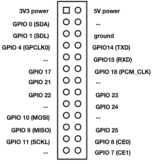
The Raspberry Pi expansion port pinout is:
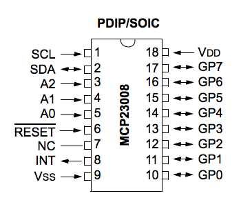
The MCP23008 pins are:
There are 4 wires connect the RPi to the MCP23008:
- SDA RPi pin 3 to MCP23008 pin 2
- SCL RPi pin 5 to MCP23008 pin 1
- 5V RPi pin 2 to MCP23008 pin 18
- GND RPi pin 6 to MCP23008 pin 9
Note that I’m powering the chip from 5V instead of the 3.3V because I want to power the motor windings at 5V. I have read that there is no problem connecting 3.3V and 5V circuits over I²C.
In addition you must make the following connections on the chip. It is very important that you do not let the address pins or the reset pin float!
- MCP23008 address pins 3,4,5 to Vdd or Vss to set the bus address.
- MCP23008 reset pin 6 to Vdd. Pull it high.
You do not need current limiting resistors on the address or reset pins and the RPi has built-in pull-up resistors on SDA and SCL so you do not need to provide them. Too easy, right?
The I²C 7-bit address will be binary [ 0 0 1 0 A2 A1 A0 ] so
if all address lines are pulled to ground it will be at 0x20, if they
are all high, it will be at 0x27. I²C addresses are sometimes confusingly
left-shifted 1 bit and expressed as 8-bit addresses, which are 2x the 7-bit
address, like this [ 0 1 0 A2 A1 A0 0 ]. Can’t we all just get along?
Side note - if you are reading I²C protocol diagrams, I²C sends the most
significant bit first.
Step 4 - Probe It
Power up and repeat the i2cdetect command. This time you should
see device on the bus. Mine is at 0x20 because I pulled all of the
address lines low.
pi@raspberrypi ~ $ sudo i2cdetect -y  0
     0  1  2  3  4  5  6  7  8  9  a  b  c  d  e  f
00:          -- -- -- -- -- -- -- -- -- -- -- -- --
10: -- -- -- -- -- -- -- -- -- -- -- -- -- -- -- --
20: 20 -- -- -- -- -- -- -- -- -- -- -- -- -- -- --
30: -- -- -- -- -- -- -- -- -- -- -- -- -- -- -- --
40: -- -- -- -- -- -- -- -- -- -- -- -- -- -- -- --
50: -- -- -- -- -- -- -- -- -- -- -- -- -- -- -- --
60: -- -- -- -- -- -- -- -- -- -- -- -- -- -- -- --
70: -- -- -- -- -- -- -- --
You can read the IODIR register (0) which should return all 1’s (all pins configured as inputs), and the OLAT register (10 or 0xA) which should return all 0’s.
pi@raspberrypi ~ $ sudo i2cget -y 0 0x20 0
0xff
pi@raspberrypi ~ $ sudo i2cget -y 0 0x20 10
0x00
Step 5 - Spin a Motor!
I wired up a VID29 to pins GP0 to GP3 on the driver chip and kludged together some C code to cycle through the 6 signal states used to drive the motor. I’m using a VID29 motor with the stops removed so I can let it spin continuously without hitting the stop. The test code is here.
$ sudo ./i2ctest
Register 0 = 255
Register 1 = 0
Register 2 = 0
Register 3 = 0
Register 4 = 0
Register 5 = 0
Register 6 = 0
Register 7 = 0
Register 8 = 0
Register 9 = 0
Register 10 = 0
done
error writing i2c gpio register
error writing i2c gpio register
...
Yeah, so those errors aren’t good. The results of reading the 10 registers look fine, but as soon as it starts trying to turn the motor we are getting errors. After some fiddling I confirmed that the errors only happen when the motor is attached, so it looks like the RPi’s 5V power rail isn’t able to supply the necessary current. This is not actually a surprise, and it isn’t a big problem either.
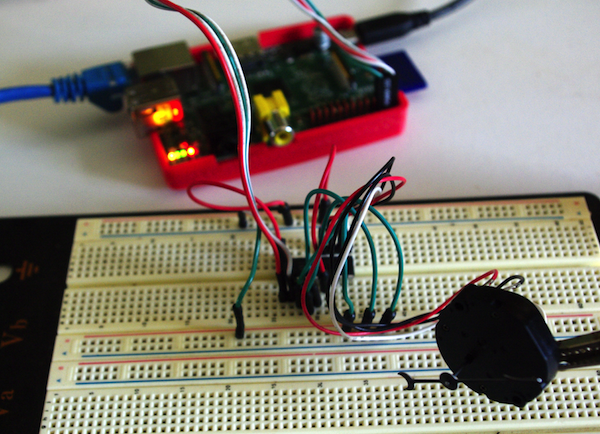
I happen to have a beefy 10A 5V supply on the bench, so used that to power the MCP23008. Problem solved, motor turns, errors are gone.
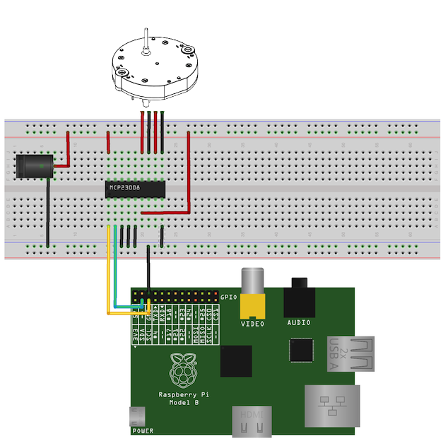
This is the final circuit.
Speed Tests
NOTE: Since writing this I discovered that the supply voltage used in these tests was down-regulated to around 3.9V instead of 5.0V, which accounts for the disappointing speeds noted below. I will repeat these tests when I get a chance. Initial tests indicate that at a full 5.0V the motor has roughly the same speed limits when driven by the MCP23008 as it does when driven directly from Arduino digital IO ports. It is also worth noting that the overhead for sending each motor pulse update over I²C is about 400μS. This could probably be improved using byte mode (to avoid sending the register address over I²C on each update) or by selecting a higher I²C baud rate.
I have previously measured the maximum speed that the Arduino can turn a VID29 stepper when driving directly from the I/O pins, and found it was a little over 500°/S.
I repeated these tests with the RPi and found a maximum speed of around 215 °/S, presumably lower because of the reduced current capacity. (Correction - it is due to an accidentally low supply voltage. See above.) I tried ganging two pins from the MCP23008 to each of the motor pins, thinking I might squeeze a little extra current out of the chip. That boosted the maximum speed a little, but still fell well short of the Arduino.
| System | Min μS/step | Max °/S |
|---|---|---|
| Arduino | 649 | 513 |
| RPi + MCP23008 | 1550 | 215 |
| RPi + MCP23008 paired pins | 1426 | 233 |
Conclusions
The MCP23008 will indeed drive a Switec X25.168 (or clone) but the limited current capacity means that the motor’s maximum speed is noticably less than when driving from an Arduino.
If you aren’t bothered by the reduced maximum speed, you can drive lots of these little stepper motors without running out of I/O pins. One very tidy solution would be to use the Centipede Shield which would in theory drive up to 16 motors per shield - although at some point you will probably hit CPU limits trying to service the I/O.
Not surprisingly, the 5V power rail on the Raspberry Pi isn’t up to powering even one micro stepper, but the MCP28003 conveniently allows us to inject 5V power from a separate supply, so that isn’t a serious problem.