Here’s a quick overview of the rotary encoder I/O class in the py-gaugette library.
The encoder I’m using is a 2-bit quadrature-encoded rotary encoder,
available from Adafruit.
The datasheet is here.
The documentation for this encoder says that it gives 24 pulses per 360° rotation, which I interpreted to mean 24 resolvable positions, but after trying it I see that it has 24 detent positions, and between each detent is a full 4-step quadrature cycle, so there are actually 96 resolvable steps per rotation. This unit also includes a momentary switch which is closed when the button is pushed down. Takes a solid push to close the switch.
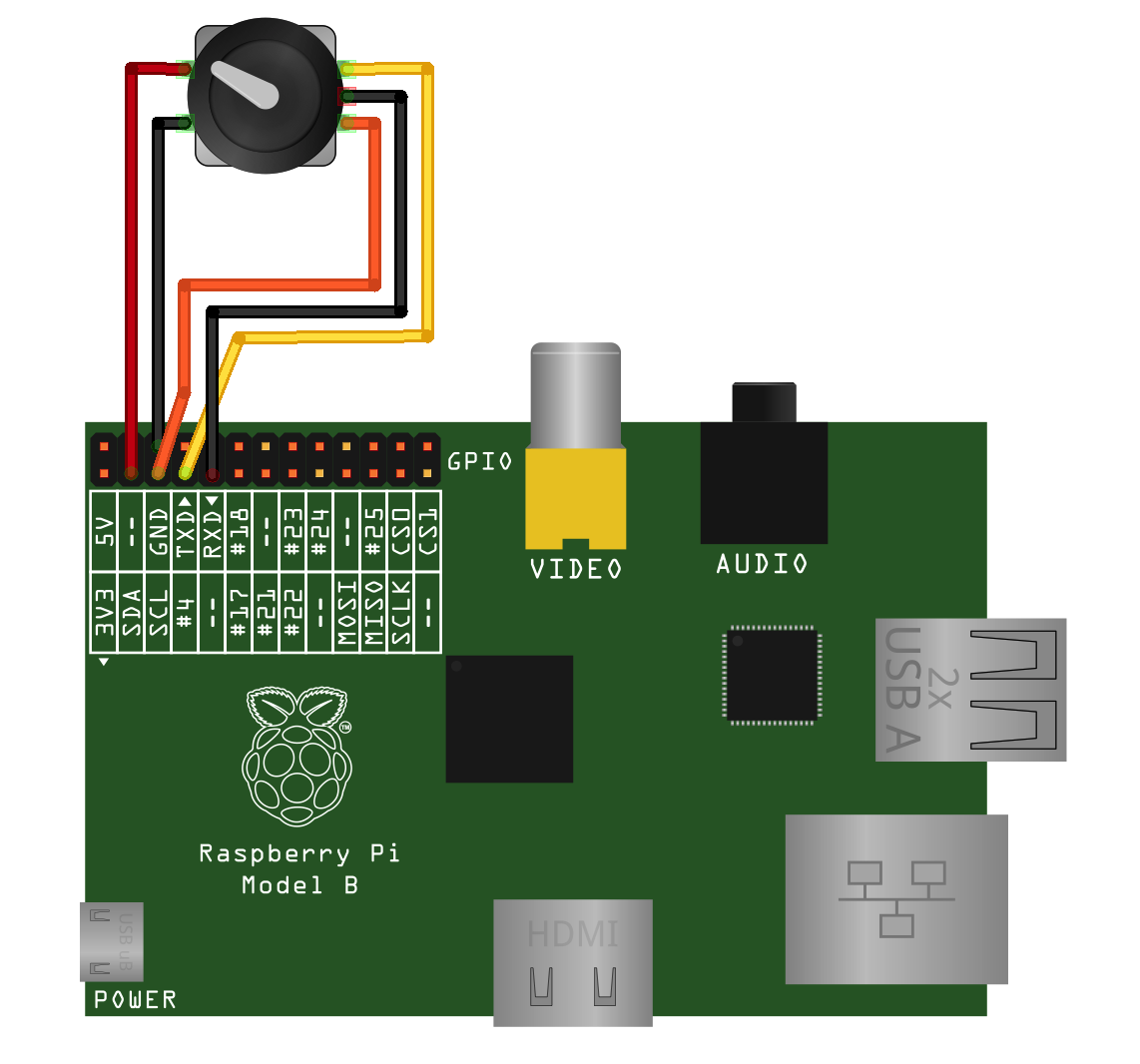
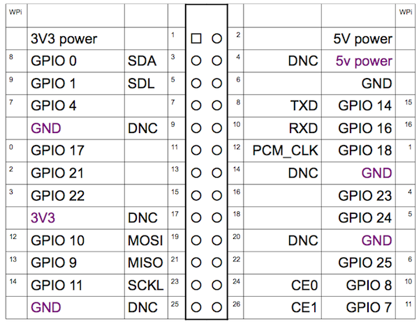
The diagram above shows how I’ve connected the rotary encoder to the Raspberry Pi. I’m using pin 9, one of the “Do Not Connect” (DNC) pins to get a second ground pin for convenience. Eben made a public commitment to keep the extra power and ground pins unchanged in future releases, so I think it is safe to publish circuits using them. Right? Here’s a pinout highlighting the functions of the DNC pins, along with the wiringpi pin numbers.
Decoder Logic
The implementation configures pins A and B as inputs, turns on the internal pull-up resistors for each, so they will read high when the contacts are open, low when closed. The inputs generate the following sequence of values as we advance through the quadrature sequence:
| SEQ | B | A | A ^ B |
|---|---|---|---|
| 0 | 0 | 0 | 0 |
| 1 | 0 | 1 | 1 |
| 2 | 1 | 1 | 0 |
| 3 | 1 | 0 | 1 |
One non-obvious detail here: the library uses the bitwise xor value A ^ B to
efficiently transform the input bits into an ordinal sequence number. There is
no reason behind the xor other than it gives us the bit sequence we want.
seq = (a_state ^ b_state) | b_state << 1
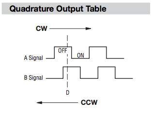
Because we are pulling our inputs high and shorting to ground when the contacts close, our inputs for A and B are actually inverted against those shown in Quadrature Output Table figure above. It turns out you can ignore this inversion in the decode logic; inverting the signals moves the quadrature half a cycle forward, but makes no difference at all to the decode logic.
Once the library has computed the sequence value, it determines the direction of movement by comparing the current sequence position against the previous sequence position, like this:
delta = (current_sequence - previous_sequence) % 4
which will yield values in the range 0 through 3, interpreted as follows:
| delta | meaning |
|---|---|
| 0 | no change |
| 1 | 1 step clockwise |
| 2 | 2 steps clockwise or counter-clockwise |
| 3 | 1 step counter clockwise |
If we get a value of 2, we know we have missed a transition (oops!) but we don’t know if the encoder has turned clockwise or counter-clockwise. In this case the library assumes the direction is the same as the previous rotation. Of course if the encoder has actually moved 3 steps between reads, it will decode as 1 step in the wrong direction. You can only fix this by polling faster or using interrupts.
Polling Vs Interrupts
The current implementation of the RotaryEncoder class uses polling to monitor the inputs rather than
using GPIO interrupts. It looks like the plumbing is in place within wiringpi to use interrupts on GPIOs,
but I’ll leave that for another day. Instead I have included an optional worker thread class that can be used
to monitor the inputs, leaving the main thread free to go about its business.
The push switch is handled by a separate Switch class that doesn’t do anything clever like debounce - it just reads and returns the current switch state.
Here’s how to read the rotary encoder and switch without starting a worker thread.
import gaugette.rotary_encoder
import gaugette.switch

A_PIN  = 7
B_PIN  = 9
SW_PIN = 8

encoder = gaugette.rotary_encoder.RotaryEncoder(A_PIN, B_PIN)
switch = gaugette.switch.Switch(SW_PIN)
last_state = None

while True:
    delta = encoder.get_delta()
    if delta!=0:
        print "rotate %d" % delta

    sw_state = switch.get_state()
    if sw_state != last_state:
        print "switch %d" % sw_state
        last_state = sw_state
Spin the knob and you should see something like this:
$ sudo python rotary_worker_test.py
switch 0
rotate 1
rotate 1
rotate -1
...
Using the class as shown above, you must call encoder.get_delta() frequently enough
to catch all transitions. A single missed step is handled okay, but 2 missed steps will
be misinterpreted as a single step in the wrong direction, so if you turn the knob too quickly
you might see some jitter.
To ensure the inputs are polled quickly enough, even if your application’s main thread
is busy doing heavy lifting, you can use the worker thread class
class to monitor the switch positions. Using the worker class is trivial;
instantiate RotaryEncoder.Worker instead of RotaryEncoder with the same
parameters, and call the start() method to begin polling - only lines 8 and 9 below have changed.
import gaugette.rotary_encoder
import gaugette.switch

A_PIN  = 7
B_PIN  = 9
SW_PIN = 8

encoder = gaugette.rotary_encoder.RotaryEncoder.Worker(A_PIN, B_PIN)
encoder.start()
switch = gaugette.switch.Switch(SW_PIN)
last_state = None

while 1:
    delta = encoder.get_delta()
    if delta!=0:
        print "rotate %d" % delta

    sw_state = switch.get_state()
    if sw_state != last_state:
        print "switch %d" % sw_state
        last_state = sw_state
Here’s a video showing the rotary encoder at work. In this case I use the main thread to service the OLED scrolling, with the worker thread keeping an eye on the rotary encoder. There is another worker thread that manages the RGB led transitions.