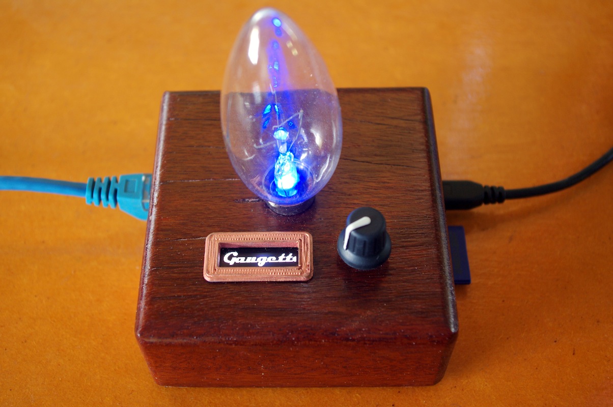
Gaugette Time Clock
This build combines a Raspberry Pi with a rotary-encoder, an RGB LED and an OLED character display to create a time clock that logs my time on tasks directly to a Google Docs spreadsheet.
Motivation
Whenever I have to record time against projects, I find it really hard to diligently keep my time records up to date. Maybe with a purpose-built time clock I will keep better records? Hey, it could happen!
Overview
The off-the-shelf components:
- Raspberry Pi model B Rev 1 - Adafruit has the Rev 2 board.
- 128x32 SPI OLED display - Adafruit
- Rotary Encoder - Adafruit
- 5mm RGB LED - Sparkfun
- Occidentalis 0.2 - Adafruit
- 6” Female/Female jumper wires - Adafruit
- 3” Female/Female jumpers wires - Little Bird Electronics or Adafruit
I used a common cathode LED from Sparkfun. You could use Adafruit’s common anode equivalent with minor code changes.
The theory of operation is pretty simple:
- at start-up, it pulls a list of jobs from a Google Docs spreadsheet,
- rotating the knob scrolls through the list of jobs,
- clicking the knob logs a start time or end time in the spreadsheet.
The Case
The top of the case is made from a single block of wood.

The bottom of the block has been hollowed out to house the RPi board. The RPi sits in a plastic carriage that screws to the bottom of the block. I have not provided access to the HDMI, audio or video ports on the RPi since I’m not going to use them.

The carriage for the Raspberry Pi was designed in OpenSCAD and printed on a Makerbot Replicator. The RPi board doesn’t have mounting holes, so the carriage has edge-clips to grasp the board. The posts at the corners were originally intended to screw the carriage to the block, but I found that to be impractical, so I added the two tabs at the bottom and routed out matching recesses in the block. I left the posts there because they make the carriage look a little more interesting. Or because I was too lazy to remove them, I’ve heard it both ways.

The OpenScad sources and STL files for the base are available from Thingiverse.
The Circuit
I’m using two of the ground pins originally documented as Do Not Connect (DNC). The extra grounds are really convenient, and Eben has publicly committed to keeping these available in future board revisions.
It’s worth pointing out that I deliberately selected GPIO pin 5 for the push
button because of the Raspberry Pi Safe
Mode feature. If
you have a recent firmware release, you
can boot your RPi in safe mode by holding the knob down (shorting pin 5 to
ground) when you power up. In truth my intention here is not so much to make
safe mode available (I’ve never needed it) but to make sure that pin 5 is not
unintentionally shorted to ground at boot time, as it could be if you used it
for one of the quadrature encoder inputs. Yep, that happened. After I upgraded
to the version of firmware that supports safe mode my box stopped booting.
Lesson learned; be careful with pin 5, or disable safe
mode by adding
avoid_safe_mode=1 to /boot/config.txt.
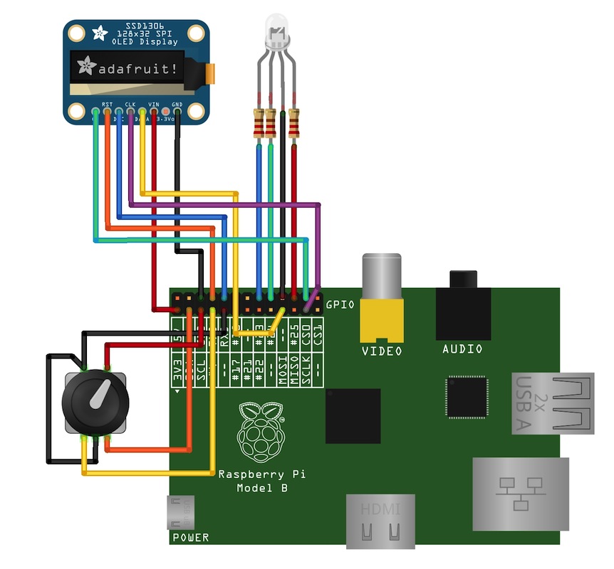
For most of the GPIO connections I cut pre-terminated Female Female jumper wires in half and soldered the cut end to the component. I already had header pins on the SSD1306 OLED module, so I used 3” pre-made cables from Little Bird Electronics. It is crucial to keep wiring short and well insulated so that it will all pack in neatly and without shorts when the case is closed up.

RGB LED Indicator
For this device I wanted a large, diffuse and interesting state indicator built around an RGB LED. I use the WiringPi soft PWM library to drive the LED, and the py-gaugette RgbLed class makes it easy to do animated colour transition loops. My first prototype was made from the back of a GU10 light bulb. The bulb glass is thick and diffuses the light nicely, and I thought the terminals would make cool capacitive switches.

I liked that a lot, but ultimately settled on a long oven light which had a more compact footprint. It gives elegant curving internal reflections which look quite nice.
When I cut the metal tip of the bulb off with a Dremel I expected to be able to remove the burned-out filament, but discovered this bulb (like most others I would guess) is made with an inner glass plug that encases the filament wires and seals the bulb. It isn’t easily removed, but has a hollow neck just big enough to receive an LED. So the filament stays. Maybe I should have used a new bulb!
I trimmed the red, green and blue leads on the LED quite short and soldered a 270Ω current-limiting resistor to each one. This keeps the resistors tucked up away from the board. I then added connector wires to each lead, pushed the LED up into the bulb neck and pumped some hot glue in to keep it all in place.
I’ve seen advice suggesting I should have selected different values for the resistors to get optimal white balance. I didn’t bother. Colour balance is fine. I aint bovvered.

Rotary Encoder
I documented the encoder library in a previous post. I’m using the py-gaugette RotaryEncoder.Worker class to poll the encoder GPIOs in the background which keeps the application code very simple.
128x32 SSD1306 OLED Display

I’ve written about using these great little 128x32 OLEDs from Adafruit before. Mounting it in the block was a challenge. I used a router on the inside of the case to thin the material down to just a few mm over an area big enough to place the PCB. I then cut a rectangular hole for the display using a Dremel, file and scalpel, taking great pains not to crack the thin wood. I couldn’t see a practical way to use the mounting holes so I hot-glued the board in place. I positioned it with the display powered up showing a test pattern so I could line up the active part of the display with the hole.
The bezel was printed on a Makerbot Replicator and painted with Plaid brand copper Liquid Leaf. I’ve been looking for a metallic paint that wouldn’t dissolve the ABS. Liquid Leaf is xylene-based, which should be safe for ABS, although maybe not so safe for humans.

The effect of metallic paint on the printed surface is interesting; it highlights the individual filaments in the print. I like it. It would be possible to reduce the relief by brushing the surface with acetone before painting, but I think the sharp relief is good for what I’m doing here.
Cooling
It occurred to me fairly late in this build that I hadn’t provided for any air flow to help cool the processor. That got me to wondering, then to worrying… am I cooking my Pi? And is there no end to the bad pie puns?
Fortunately a recent firmware update provided a tool that allows us to measure the CPU temperature in code, so I did a little experiment. I recorded the temperature using vcgencmd.
while :; do /opt/vc/bin/vcgencmd measure_temp; sleep 3; done
I ran this loop from a cold boot for 25 minutes, first with the top off, then again (after letting the system cool down) with the case closed up tight. For the record the ambient temperature in my office was around 26°C.

The results show that the closed box adds about 4°C to the CPU temperature at idle. I tried removing the bulb from the centre of the cover to allow hot air to be convected away, but that made no measurable difference in temperature.
These temperatures were taken at idle. My application code runs around 20% CPU utilization. With application running and the lid off the temperature settles in around 46°C, and with the lid on at around 51°C.
Based on these results I’m happy to ignore air flow for now. 51°C isn’t worryingly high, and it looks like it would take a lot of work to improve air flow enough to make an appreciable difference.
Software
The code for all of the I/O devices used here is available in the py-gaugette library. I will release the application source soon; there are a few loose ends I want to tidy up first.
All Together Now
In the video below, the LED colours are as follows:
- purple is idle - time not being logged
- slowly pulsing blue is active - time is being logged against a task, pulses slowly
- flashing is busy - updating the spreadsheet via Google Docs
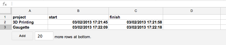
The resulting spreadsheet looks like this: