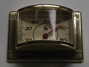
 This weekend I opened up one of the cheap-but-funky thermometers/hygrometers
from Lets Make Time
and replaced the thermometer mechanism with the
Arduino-controlled Switec X25.168 stepper.
The thermometer and hygrometer are installed
in identical one-part plastic housings with no screws
or seams, so it wasn’t clear how to crack them open.
This weekend I opened up one of the cheap-but-funky thermometers/hygrometers
from Lets Make Time
and replaced the thermometer mechanism with the
Arduino-controlled Switec X25.168 stepper.
The thermometer and hygrometer are installed
in identical one-part plastic housings with no screws
or seams, so it wasn’t clear how to crack them open.
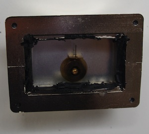 I used a Dremel to cut away the back panel giving access to the
thermometer mechanism, but to my surprise the dial face was still firmly
locked in place. After a bit
of poking around I discovered that I could push the whole assembly out
forward - in fact the plastic lens is only held in by friction, and
the dial and mechanism are held in by the lens. No cutting was
required. #LFMF
I used a Dremel to cut away the back panel giving access to the
thermometer mechanism, but to my surprise the dial face was still firmly
locked in place. After a bit
of poking around I discovered that I could push the whole assembly out
forward - in fact the plastic lens is only held in by friction, and
the dial and mechanism are held in by the lens. No cutting was
required. #LFMF
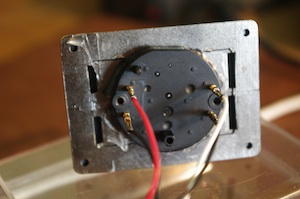
 This turned out to be important because after careful measurement I realized
that the motor would have to be mounted snugly against the the back of the housing to
leave the drive shaft protruding enough to attach a needle. The plastic panel I cut away
would have been ideal to screw the motor to.
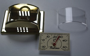
Starting again with an undamaged housing, I gently pried out the plastic lens, removed the face and mechanism.
This time I only cut away enough plastic on the back to allow the drive shaft to pass through.
This turned out to be important because after careful measurement I realized
that the motor would have to be mounted snugly against the the back of the housing to
leave the drive shaft protruding enough to attach a needle. The plastic panel I cut away
would have been ideal to screw the motor to.
Starting again with an undamaged housing, I gently pried out the plastic lens, removed the face and mechanism.
This time I only cut away enough plastic on the back to allow the drive shaft to pass through.
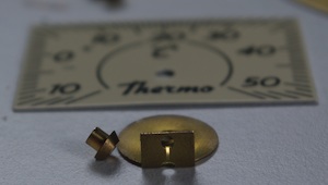 The needle and the bi-metal thermometer coil came off the face easily enough, but the mounting for the coil
is a crafty two-piece deal that mounts through the centre of the dial. It appeared to be
assembled a bit like a rivet, and a couple of solid blows from the back with a punch
released it cleanly from the dial face.
The needle and the bi-metal thermometer coil came off the face easily enough, but the mounting for the coil
is a crafty two-piece deal that mounts through the centre of the dial. It appeared to be
assembled a bit like a rivet, and a couple of solid blows from the back with a punch
released it cleanly from the dial face.
 I originally intended to use screws to secure the stepper to the back of the housing, but
there isn’t much tolerance for positional
error, which made me nervous. Instead I used the conical rivet-thingy to precisely align the motor drive shaft in hole in the dial and held it all in place while I hot-glued it to the back of the case. Alignment was spot-on the the motor seems to be solidly secured. So far so good.
I originally intended to use screws to secure the stepper to the back of the housing, but
there isn’t much tolerance for positional
error, which made me nervous. Instead I used the conical rivet-thingy to precisely align the motor drive shaft in hole in the dial and held it all in place while I hot-glued it to the back of the case. Alignment was spot-on the the motor seems to be solidly secured. So far so good.
Next I wired up the Arduino and zeroed the motor against the low stop and put the needle on. There were some unexpected complications at this point. The motor has a sweep of 315 degrees, but this dial only allows about 230 degrees of needle movement. I modified the library to support a soft range limit to avoid exceeding 230 degrees, while still running through a full 315 degrees during reset.
While trying to calibrate the dial I found the needle slipping at times, especially under vibration caused by the power-on reset or slow stepping. With the needle slipping calibration was impossible. I tried applying the smallest drop of hot glue I could manage to the back of the needle. That really didn’t work - the tiny irregular mass between the needle and the dial face would sometimes bind against the dial face, causing more problems.
I believe the needle hole is dished a little, so I removed the needle, cleaned the glue away, and smacked it with a hammer to flatten out the dish and close up the hole. That worked a little too well and I had to ream the hole out a bit with a thumb tack. Now the needle is nice and snug, no slippage.
So here’s how it looks assembled. Calibration is slightly out, but I’m going to make a new dial face anyway, so no need to sweat about that.