The logic in the advance() function of the
Switec X25 library
steps the motor forward or backward one step, then computes the delay in
microseconds until the next step is due. This logic determines the acceleration curve and
maximum speed of the needle. My first cut at this
code used floating point arithmetic to model this as time/accel/velocity problem. The
motion was nice and smooth, but it was overkill, and consumes too many precious Arduino
compute cycles. When driving multiple motors, this will create an artificial ceiling on the
maximum motor speed.
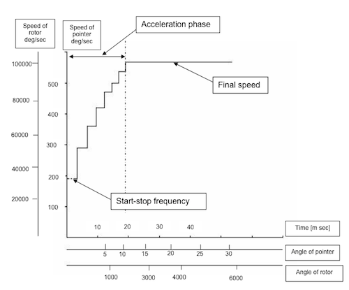
I’ve rewritten that logic to use a simple lookup table instead.
This is a fairly obvious approach, but it was
reassuring to see similar approaches recommended in both the
VID 29 documentation
and the MCR MR1107 data sheet
.
The acceleration curve is defined as pairs of vel,delay values:
unsigned short accelTable[][2] = {
  {   10, 5000},
  {   30, 1500},
  {  100, 1000},
  {  150,  800},
  {  300,  600}
};
We maintain a variable vel (which isn’t actually velocity,
but is a surrogate for velocity) that increments
each step under acceleration, and decrements each step under deceleration.
When stationary, vel is zero. After 1 step of acceleration it is 1.
For simplicity I’ve made the acceleration and deceleration curves identical
so they can share the same lookup table.
To determine the inter-step delay at any given value of vel, we find
the first table entry such that accelTable[i][0] < vel. In practice this means that the
motor will step at 5000 µS intervals for 9 steps, then 1500 µS
steps for the next 30 steps, 1000 µS for the next 100 steps, and so on.
The peak speed with a delay of 600 µS equates to 1666 Hz step rate
or about 500 degrees per second.
The motion control logic first determines if the motor is subject to acceleration,
at full speed, or deceleration and adjusts vel accordingly. Using
steps as the unit for vel makes it very
easy to determine when to declerate: when vel is greater than or equal to the number of steps
to reach our destination, we need to start decelerating.
 The new logic also ensures that if the motor is moving at
speed in one direction and is directed to a new position in the opposite direction it will
decelerate to a stop before accelerating in the opposite direction.
The constants that make up the acceleration table are constrained by the the inertia of the needle attached to the motor. The VID 29 documentation gives some recommendations for calculating these values, but I actually didn’t use that. I experimented until I found values that were within operational limits and look nice to me.
I tested this code driving 3 motors simultaneously with an Arduino Uno. All good. New code is in the library on Github.