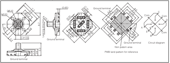
The Chumby Hacker Board has a 5-way Panasonic EVQQ7(Datasheet) dpad joystick on one corner at SW400. This post explains how to read the state of this switch via the GPIO interface.

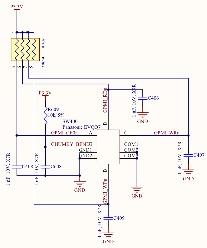
Holding the CHB such that the switch is in the south east corner as pictured here, switch A closes when the stick is pushed east, B is south, C is north, D is west and E closes when the stick is depressed. Sad dpad is sad.
The following table lists the signals and pin addresses for each of the switch contacts A-E.
- A : east : GPMI CE0n : BANK2_PIN28
- B : south : GPMI WPn : BANK0_PIN23
- C : north : GPMI WRn : BANK0_PIN24
- D : west : GPMI RDn : BANK0_PIN25
- E : down : PWM4 : BANK_1_PIN30 (aka CHUMBY BEND)
Each of these inputs is pulled high, and driven low when the switch is closed. 1nF capacitors on each signal line prevent switch bounce.

To read these inputs using GPIO you must make 3 calls:
- set the associated pin to GPIO mode,
- disable output on the pin,
- read the associated GPIO register to get the value
For example to read switch E using the GPIO library from the Chumby Sampler code:
1 2 3 4 5 6 7 8 9 10 11 12 13 14 15 16 17 18 | |
Complete sample code for reading the state of all 5 switches is available in the Chumby Sampler.