
Adafruit’s lovely little 128x32 monochrome SPI OLED module uses a SSD1306 driver chip (datasheet), and Adafruit have published excellent tutorials and libraries for driving this from an Arduino.
When asked in their forum about Raspberry Pi support, Adafruit have said that there is a huge backlog of libraries to port to the RasPi and (they) don’t have any ETA on the SSD1306.
I’m working on a project that was originally intended for an Arduino, but I’ve decided to switch to the Raspberry Pi, so I need to get this display working with the Pi. To that end, I’ve partially ported Adafruit’s SSD1306 library to Python for the Raspberry Pi. The port is partial in that:
- it only supports the 128x32 SPI module (unlike the original that supports the I²C and 128x64 modules) and
- it only supports pixel and text drawing functions (no geometric drawing functions).
Signal Levels
The SSD1306 operates at 3.3V, and the Adafruit module has built-in level-shifters for 5V operation. However I want to drive it at 3.3V from the Pi, and I wasn’t confident from the documentation that it would operate at 3.3V without modification. However the back-side silkscreen says very clearly 3.3 - 5V and I can confirm it works very happily with both Vin and signalling at 3.3V.
SPI Signals
In SPI nomenclature MISO is master in, slave out, MOSI is master out, slave in. The SSD1306 module is write-only using SPI, and so there is no MISO connection available, and MOSI is labelled DATA on the module. Of course SPI always reads while it writes, but it is fine to leave MISO disconnected. It will be pulled low, so if you ever looked at the data you would see all zeros.
The D/C (Data/Command) signal on the module is not part of the SPI specification, and it took a little experimenting to understand exactly what it is used for. The data sheet says “When it is pulled HIGH (i.e. connect to VDD), the data at D[7:0] is treated as data. When it is pulled LOW, the data at D[7:0] will be transferred to the command register.”
Initially I supposed data to include the argument bytes that follow the opcode when sending multi-byte commands. For example the “Set Contrast Control” command consists of a one-byte opcode (0x81) followed by a one-byte contrast value, so I was sending the first byte with D/C high, and pulling it low for the argument byte. Wrongo! That’s not what they mean by data; keep the D/C line high for all bytes in a command, and pull it low when blitting image data into the image memory buffer. Simple as that.
Platform
I’m running Python 2.7.3 on a Rasberry Pi Model B (v1) with the following software:
- Occidentalis 0.2 boot image,
- WiringPi-Python for python access to the GPIO pins,
- py-spidev for python bindings to the spidev linux kernel driver.
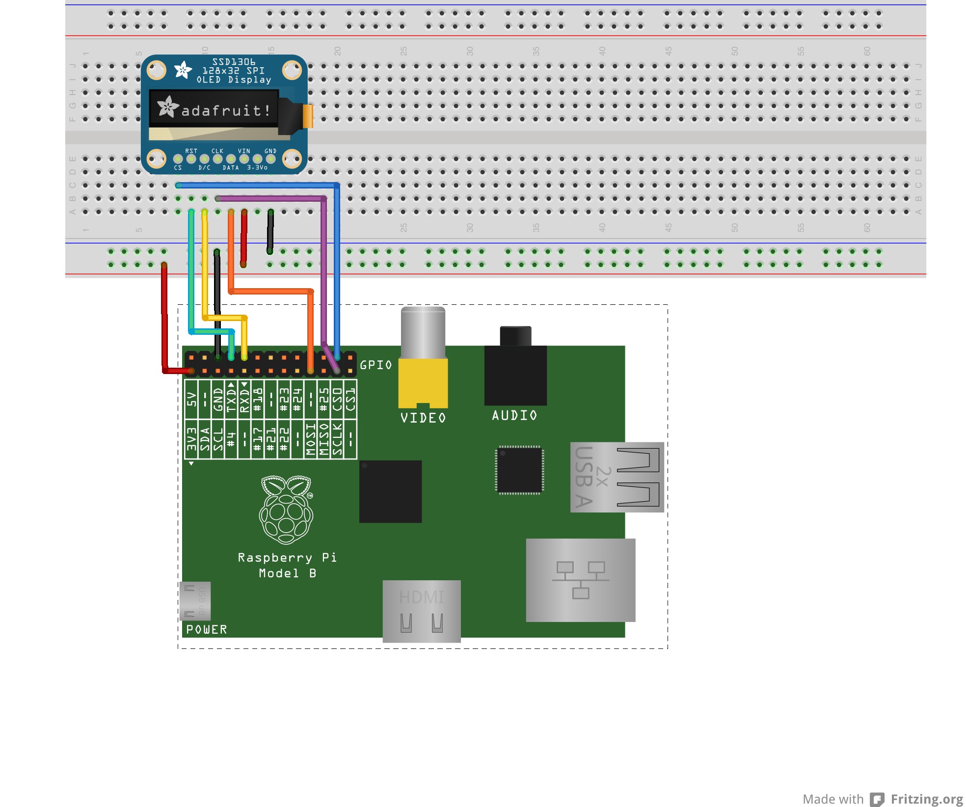
Wire Up
Here’s how I’ve wired it up. You can freely change the GPIOs for D/C and Reset.
Test Code
Note that pin numbers passed in the constructor are the wiring pin numbers, not the connector pin numbers! For example I have Reset wired to connector pin 8, which is BCP gpio 14, but wiringPi pin 15. It’s confusing, but just refer to the wiringPi GPIO table.
The python library for the SSD1306 has been rolled into the py-gaugette library available on github.
The test code below vertically scrolls vertically between two display buffers, one showing the current time, one showing the current date.
This sample code is included in the py-gaugette library.
import gaugette.ssd1306
import time
import sys

RESET_PIN = 15
DC_PIN    = 16

led = gaugette.ssd1306.SSD1306(reset_pin=RESET_PIN, dc_pin=DC_PIN )
led.begin()
led.clear_display()

offset = 0 # buffer row currently displayed at the top of the display

while True:

    # Write the time and date onto the display on every other cycle
    if offset == 0:
        text = time.strftime("%A")
        led.draw_text2(0,0,text,2)
        text = time.strftime("%e %b %Y")
        led.draw_text2(0,16,text,2)
        text = time.strftime("%X")
        led.draw_text2(8,32+4,text,3)
        led.display()
        time.sleep(0.2)
    else:
        time.sleep(0.5)

    # vertically scroll to switch between buffers
    for i in range(0,32):
        offset = (offset + 1) % 64
        led.command(led.SET_START_LINE | offset)
        time.sleep(0.01)
About Fonts

This test code uses the 5x7 bitmap font from the Adafruit GFX library scaled to x2 and x3. It works, but Steve Jobs would not approve! It isn’t taking advantage of the very high resolution of these lovely little displays. Larger fonts with kerning would be a great addition.