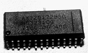
This article demonstrates a modification of the Arduino SwitecX25 driver library
to use a AX1201728SG quad driver chip (equivalent to the X12.017 or VID6606).
This chip offers some significant advantages over driving the motor directly:
- it uses microstepping to provide smoother positioning - 12 steps per degree rather than 3.
- it requires only two GPIO pins per motor (plus one global reset pin)
- it protects the microprocessor from the inductive effects of the motor coils
- it places lower current requirements on the microprocessor

I just dusted off an old project that uses
Google’s OAuth 2.0 for Devices API to
authenticate against Google Docs, and cleaned up my implementation.
OAuth2ForDevices is really useful for IoT projects
that use Google APIs. I’m using it for a device that records data directly a Google Sheet.
While the API itself is pretty straight forward, getting the implementation 100%
battle-hardened takes a bit of work and iteration, so I’ll share here what I’ve learned.
If you are coding in Python, you might find the OAuth class in the
py-gaugette library useful.
I’ve made some major changes to the py-gaugette library to address several issues that have accumulated over time, namely:
added interrupt-driven option to rotary encoder fully Python 3 compatible works with current version of Py-WiringPi uses dependency injection for GPIO and SPI interfaces updated Google Sheets code to use new API Dependency Injection for GPIO and SPI Classes that interact with the GPIO or SPI interfaces now take an instance of that interface as a parameter to the constructor.
What Are We Doing Here?
In an earlier post I described how to use the py-gaugette library to drive an Adafruit 128x32 monochrome OLED display from a Raspberry Pi, and a followup article added high-quality fonts.
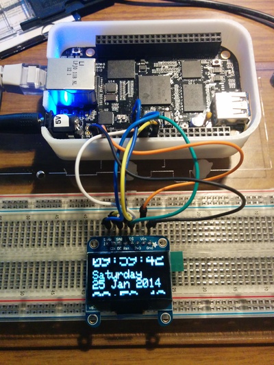
I’ve now updated the library to run on the BeagleBone Black and to support Adafruit’s larger 128x64 display.
On the BBB py-gaugette uses Adafruit’s BBIO library for SPI and GPIO access.
 While working through a few queries about the rotary encoder library,
it became evident that it would help to have a better test application to diagnose wiring issues.
While working through a few queries about the rotary encoder library,
it became evident that it would help to have a better test application to diagnose wiring issues.
I’ve committed
a better version of rotary_test.py that writes out a
comprehensive table of state information, updated whenever anything changes.


 While working through a few queries about the